Revisiting the Psion Bluetooth Keyboard
My take on a Psion bluetooth keyboard has been in the works since 2018. It’s one of my first hardware projects and, if I’m honest with myself, was a litte beyond my abilities at the time. There were just too many new things all at once: microcontrollers, 3D printing, and PCB design.
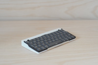
The PsiBoard, while working, has never felt complete
Now that I’ve a little more experience behind me, I’m going to have a go at finishing it—I receive a constant trickle of emails from folks intereted in building their own, and I’d love to be able to offer a complete set of parts and instructions.
Shifting Sands and a New Direction
The world of custom keyboards has moved on significantly since 2018, with devices like the Pro Micro and it’s cousin the nice!nano becoming the go-to microcontrolers, supported by a wide range of off-the-shelf customizable firmware.
Moving forwards, I’m going to use ZMK and a nice!nano. This is a combination I’ve experience with from my work on the Little Luggable, and it should allow me to foucs on the electronics and the industrial design, rather than spending my days working around already-solved firmware issues.
Electronics
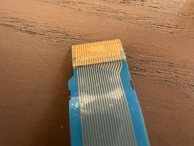
The Psion Series 5/5mx keyboard connects using a 20-pin ribbon cable
When I last worked on the PsiBoard, my understanding of the keyboard matrix was as follows (ribbon cable pin numbering given in parentheses):
| Col 01 (15) | Col 02 (11) | Col 03 (10) | Col 04 (9) | Col 05 (8) | Col 06 (7) | Col 07 (6) | Col 08 (5) | Col 09 (4) | Col 10 (3) | Col 11 (2) | Col 12 (1) | |
|---|---|---|---|---|---|---|---|---|---|---|---|---|
| Row 01 (20) | Space | Up | . / | Left | Right | Left Shift | ||||||
| Row 02 (19) | Z | X | C | V | B | N | Right Shift | |||||
| Row 03 (18) | H | J | K | M | . ? | Down | Fn | |||||
| Row 04 (17) | Tab | A | S | D | F | G | Left Control | |||||
| Row 05 (16) | 1 | 2 | 3 | 4 | 5 | 6 | ||||||
| Row 06 (14) | U | I | O | P | L | Enter | Menu | |||||
| Row 07 (13) | Q | W | E | R | T | Y | Esc | |||||
| Row 08 (12) | 7 | 8 | 9 | 0 | Del | ‘ - |
This has 12 columns, and 8 rows, requiring 20 I/O pins—too many for most microcontrollers (the nice!nano has only 18). Previously, to work around this, I tied the modifier keys to a single column, leading to issues identifying multiple modifier keys1.
With the benefit of experience, I’ve realized that these modifier keys are intentionally broken-out to allow diodes to be introduced on each of the modifer lines to avoid exactly this problem—Psion skipped putting diodes on the flexible PCB itself, but made it possible to add them where it really matters.
Taking this into account, here’s my updated understanding of what the Series 5 keyboard matrix should look really look like:
| Col 0 (20) | Col 1 (19) | Col 2 (18) | Col 3 (17) | Col 4 (16) | Col 5 (14) | Col 6 (13) | Col 7 (12) | |
|---|---|---|---|---|---|---|---|---|
| Row 0 (15) | Z | H | Tab | 1 | U | Q | 7 | |
| Row 1 (11) | Space | X | J | A | 2 | I | W | 8 |
| Row 2 (10) | Up | C | K | S | 3 | O | E | 9 |
| Row 3 (9) | , / | V | M | D | 4 | P | R | 0 |
| Row 4 (8) | Left | B | . ? | F | 5 | L | T | Del |
| Row 5 (7) | Right | N | Down | G | 6 | Enter | Y | ‘ ~ |
| Row 6 (6,5,4,3,2,1) | Left Shift | Right Shift | Fn | Left Control | Menu | Esc |
Our new row 6 is created by tying pins 1-6 from the ribbon cable to a single pin, by means of a diode on each wire. This prevents loops in the keyboard matrix by ensuring current can only flow in a single direction through the circuit. Happily, this also only requires 15 I/O pins, leaving 3 spare pins on the nice!nano.
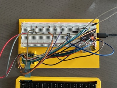
Using a breadboard to test the new modifier row and diodes
Returning to a breadboard for prototyping, I was able to confirm this all works correctly and give myself a testbed for my customized ZMK firmware.
Next Steps
With the wiring in place, the next step is to convince myself I can get all the functionality I want with the ZMK firmware, especially around power management.
-
Pressing more than one modifier key at once would lead to loops in the circuit; an issue known as key rollover. ↩