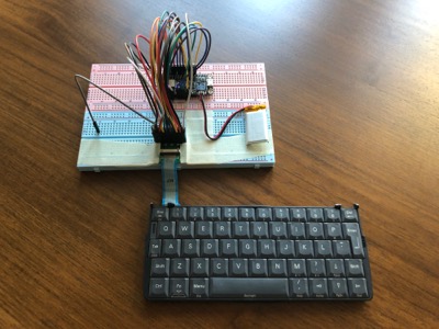
Psion Bluetooth Keyboard

The Psion Series 5 keyboard is arguably one of the best mobile device keyboards ever made. Heck, there’s even an Indiegogo campaign—the Gemini from Planet Computers—to bring it back in the form of an Android PDA.
Given the dearth of high quality small bluetooth keyboards, I’ve been wondering for quite some time if it would be possible to instead use the keyboard from a broken Series 5. A few weeks ago, I purchased such a Series 5 from eBay and set about giving it a shot.
Hardware
Upon receipt of delivery, I set about disassembling the Series 5, extracting the keyboard, and figuring out how it connects to the mainboard:

As you can see, that’s a 20 way FFC (Flexible Flat Cable). What you can’t see from the photo, is that it’s actually connected to a 22 way ZIF connector. Forutnately, the Psion Series 5 Service Manual helps clear up this discrepancy:
The Series 5 keyboard contains a total of 53 keys, organised in a conventional QWERTY arrangement. The implementation is a departure from the S3a family of products, and features a separate keyboard switch matrix assembly which slides out as the LCD screen is opened. The electrical connection between the keyboard and the main Series 5 PCB is achieved by means of a 22 way Flat Flexi Cable (only 20 ways are used for keys), fitted to a 22 way ZIF connector. The outside pins on the flexi are the grounded to allow a for a ground ring on the keyboard membrane to improve ESD protection.
This means that, while I should use a 22 way connector, it’s sufficient to connect up only 20 of those pins. Searching Amazon, I managed to find a suitable connector, and breakout board. Fortunately—given my lack of surface mount soldering experience—these both came in large quantities:

For debugging purposes, I used a breadboard to connect this to the many GPIO pins of a Raspberry Pi:

Protocol
To check that the keyboard was functional (and help figure out how it works), I reassembled the internals, and James and I spent an enjoyable few hours probing the keyboard connector with a multimeter:

We identified ground (as described in the service manual), discovered some pins were consistently high, and that the others were fluttering around low:
| Pin | Behaviour |
|---|---|
| 0 | Ground |
| 1 | ~ Low |
| 2 | ~ Low |
| 3 | ~ Low |
| 4 | ~ Low |
| 5 | ~ Low |
| 6 | ~ Low |
| 7 | ~ Low |
| 8 | ~ Low |
| 9 | ~ Low |
| 10 | ~ Low |
| 11 | ~ Low |
| 12 | High |
| 13 | High |
| 14 | High |
| 15 | ~ Low |
| 16 | High |
| 17 | High |
| 18 | High |
| 19 | High |
| 20 | High |
| 21 | Ground |
Having been involved in the OpenPsion project to port Linux to various Psion devices, I had been hopeful that this, coupled with the observations above, would suggest how to read the hardware. Sadly, while Tony Lindgren’s Series 5mx and Revo kernel patches are (wonderfully) still online, and the keyboard driver does indeed confirm the scanning matrix implied above, it’s too far removed from the hardware layout to be clear on the details.
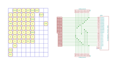
Instead, the breakthrough came when James discovered Rasmus Backman’s Psioπ project on Hackaday. In it, he details the process of building a USB adapter for the Series 5 keyboard as part of an ambitious project to build a Raspberry Pi powered Psion. It even includes the following diagram showing the layout of the keyboard matrix, and explanation of how to scan:

Reverse Engineering the Keyboard, Part I
Scanning the keyboard:
- First of all, all pins are set to Inputs. This makes them high-impedance.
- The internal pull-up resistors are enabled on the column pins. This turns them logic HIGH.
- Then, one row at a time is turned to an output and driven low.
- Check the status on the column pins. A logic LOW signal means that column is connected to the active row because that key is pressed.
- When the matrix is scanned, it is compared to the last known state. Then we send ‘pressed’ scancodes for the newly pressed keys, and ‘released’ scancodes for the keys that has been released.
- Repeat from step 3.
Reverse Engineering the Keyboard, Part IV
Coupled with our earlier pin mapping, this got us off to a great start. What proved a little confusing however was that—for my Series 5 keyboard at least—the key mapping was subtly incorrect: Fn, Menu, Esc and Ctrl did not appear to be working. After some experimentation, I realised that rows 9, 10, and 11 were, in fact, columns, leading to the following revised layout:
| Col 01 (15) | Col 02 (11) | Col 03 (10) | Col 04 (9) | Col 05 (8) | Col 06 (7) | Col 07 (6) | Col 08 (5) | Col 09 (4) | Col 10 (3) | Col 11 (2) | Col 12 (1) | |
|---|---|---|---|---|---|---|---|---|---|---|---|---|
| Row 01 (20) | Space | Up | . / | Left | Right | Left Shift | ||||||
| Row 02 (19) | Z | X | C | V | B | N | Right Shift | |||||
| Row 03 (18) | H | J | K | M | . ? | Down | Fn | |||||
| Row 04 (17) | Tab | A | S | D | F | G | Left Control | |||||
| Row 05 (16) | 1 | 2 | 3 | 4 | 5 | 6 | ||||||
| Row 06 (14) | U | I | O | P | L | Enter | Menu | |||||
| Row 07 (13) | Q | W | E | R | T | Y | Esc | |||||
| Row 08 (12) | 7 | 8 | 9 | 0 | Del | ‘ - |
Looking back at the observations made when inspecting the powered-up Series 5 with a multimeter, this allocation of pins corresponds reassuringly with the behviour we were seeing from the Psion itself.
Bluetooth
Since it’s clearly is overkill to use a Raspberry Pi, I chose the Adafruit Feather nRF52 Bluefruit LE - nRF52832 for the Bluetooth controller. It supports Bluetooth LE, has 19 GPIO pins, and an Arduino-friendly microcontroller. There’s even an Adafruit HID library and an introductory guide.
All told, the nRF52 is a great solution with only one minor limitation: the keyboard has 20 connections, but the board only 19 GPIOs pins. Fortunately the solution is a simple one: combine two of the columns into one. I chose to short pins 1 and 4, moving Ctrl onto column 9, alongside Fn.
The firmware itself is fairly simple, using a tight loop to iterate over the columns and rows as described above. These are then converted to standard Bluetooth HID events, with Psion specific modifiers being handled locally to ensure the behaviour matches the keycaps. To give as much flexibility as possible, the Fn and Menu keys are treated as Alt and Command respectively when not used for these local key combinations.
for (int c = 0; c < MAX_COLUMNS; c++) {
    int column = COLUMNS[c];

    // Pull the column low.
    pinMode(column, OUTPUT);
    digitalWrite(column, LOW);
    delay(5);

    // Iterate over the rows, reading their state.
    for (int r = 0; r < MAX_ROWS; r++) {

            int keyDown = (digitalRead(ROWS[r]) == LOW) ? 1 : 0;
            int currentKeyDown = keyboardState[c][r];

            if (keyDown != currentKeyDown) {
                    char character = CHARACTER_MAP[c][r];
                    if (character != HID_KEY_NONE) {
                            sendKey(character, keyDown);
                            keyboardState[c][r] = keyDown;
                    }
            }
    }

    // Restore the column.
    pinMode(column, INPUT_PULLUP);
}
With this, I now have a fully functional—albeit not terribly portable—keyboard. I’ve even managed to get the Psion specific key presses working, including adjusting the display brightness using the LCD contrast keys: